Above is a short video that explains why I designed my locking mechanism and how it works in the real world. Enjoy
Tuesday, February 15, 2011
Explanation Video
Above is a short video that explains why I designed my locking mechanism and how it works in the real world. Enjoy
Saturday, February 12, 2011
Evaluation
In this post I am going to look back on my project and think about how effective my design skills were and if I would change anything I’ve done during this project. I will also look in detail at my final design to see if it really is viable as an alternative locking mechanism to what is already being used in households around the world
Desirability
I think that this would be a very desirable concept for use in elderly people’s homes. The reasons I feel this to be the case are:
Desirability
I think that this would be a very desirable concept for use in elderly people’s homes. The reasons I feel this to be the case are:
- As people get older their children inevitably begin to look after them and I think that this locking mechanism is very secure due to the addition of the vertical bolts and the fact that there is more than just the key and pin system for unlocking the door (magnets).
- The lock is also so familiar to the older generation that they would barely even notice the change but it would really help them especially during the winter when there is a risk of the door jamming leaving the elderly person outside in the rain and this will prevent that situation from arising.
- The discreteness of the lock would mean that the elderly person would not feel belittled by the fact that they need to be helped with the front door as it impacts so little on aesthetics and other people aren’t aware that the help is there.
Feasibility (Technical Factors)
I am torn on this question for many reasons, which include:
- I think this locking mechanism is very feasible as the technology in it is not new and it is all used in applications similar to this one. This means that it would not be difficult to convert these technologies for use in the application I have specified.
- The way I have designed the lock in my Solidworks drawings did not take into account retrofitting (the lock I have designed would have to be built into the door during manufacture). This is because I made the housing a single piece so a carpenter would not be able to install it using the same mortising techniques that they are used to. The door would have to be cut and glued back together and this would greatly reduce the strength of the door and offer a risk to the occupants.
- The assembly would be very difficult again because of the single housing part.
- I think that if I solved the housing problem this would be a very feasible design and I would have no problem at all putting this into my house, in fact I would encourage it.
Viability (Economic Factors)
I think that this mechanism would be very economically viable because:
- This lock is not far from what is already on the market apart from the solenoid. As the current locking alternatives are relatively inexpensive and my mechanism only includes an extra solenoid I don’t think that my mechanism would end up cost much more than the current competitors.
- Security is always such a huge factor when it comes to elderly people that I feel that families would be willing to spend the money on a lock that will keep their loved ones as safe as possible and I feel that my lock offers that.
My Opinion
I am happy with the project and how it turned out. There were of course problems during my project but overall I am satisfied with the finished product.
The parts I am happy with are:
- I think the lock really fits it’s purpose and it is definitely fulfilling a need that is out their as I feel that too many elderly people have problems opening their front doors due to the doors weight and the risk of jamming in wet weather.
- My Solidworks drawing really shows off my design perfectly. I am very happy that I modelled it to a standard that really gave a clear view of how the mechanism works and the physical properties of the mechanism.
The parts I am not as happy with are:
- I think I have made my design too bulky and almost impossible to retro fit into older doors. I do not feel like it would take much changing to get it to a feasible alternative to the classic dead lock. As I said before I think it would just mean changing the housing.
What would I change if I was to do it all again?
There’s not a whole lot that I would change really.
- I feel like I came up with a very good idea for helping the elderly.
- My research was good but I could maybe have spent a little bit more time researching so that I would have realised that a single housing would not be effective.
- I think that I came up with 3 possible solutions that could have all been used as my final design.
- I am delighted with my Solidworks drawing as I was not sure if I would be able to model my design effectively but I definitely communicated the design well so the time was very worthwhile.
- I think that my notes and the means by which I have explained the design also work very well.
Finished Solution
Overview
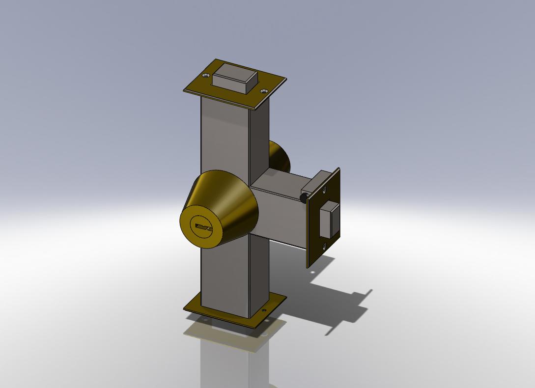
Shown here is my finishing Solidworks drawing of my lock mechanism to aid elderly people. I purposely made the housing smaller than full size (the vertical bolts would be much longer) because these drawings are simply trying to communicate my idea and I feel as though it would have been much harder to see if I had made them actual size. It is, as you can see very close to my final sketched solution. I did make a some practical changes however, these included:
1. I mounted the solenoid up against the faceplate of the horizontal bolt. The reason I did this was purely because the rubber face of the ram has to push against the door jam and it simple would not have where I had sketched it previously.
2. I added vertical bolts into the design. I did this to add extra security for the inhabitant of the house. These bolts will make it much harder for anyone to knock in the door.


Explanation of Mechanism
Sequence of events when using this locking mechanism

Exploded View of Parts

Shown here is my finishing Solidworks drawing of my lock mechanism to aid elderly people. I purposely made the housing smaller than full size (the vertical bolts would be much longer) because these drawings are simply trying to communicate my idea and I feel as though it would have been much harder to see if I had made them actual size. It is, as you can see very close to my final sketched solution. I did make a some practical changes however, these included:
1. I mounted the solenoid up against the faceplate of the horizontal bolt. The reason I did this was purely because the rubber face of the ram has to push against the door jam and it simple would not have where I had sketched it previously.
2. I added vertical bolts into the design. I did this to add extra security for the inhabitant of the house. These bolts will make it much harder for anyone to knock in the door.

Explanation of Mechanism
Sequence of events when using this locking mechanism
- Door is closed and locked
- Person arrives at the door and takes out their key
- The key is inserted into the barrel
- The key is turned clockwise which in turn rotates the barrel 90°
- The barrel is attached to the cam shaft which is in turn attached to the 3 cams. Once the barrel is rotated the cams do the same. When the cams turn the 90° they retract the 3 bolts.
- There is also a magnetic contact in the barrel so that when the barrel is in the open position, with a key in it, the solenoid pushes out against the door jam. This action causes the door to open slightly (enough to get it past the jam).
- The operator pushes the door in and they walk into the house.
- Once inside the house the operator closes back in the door and locks it again by turning the key back 90° anti-clockwise.

Exploded View of Parts

Manufacture - Class 5
Assembly

This is the class I have been really looking forward to. I finally got to assemble my lock and see it in action. The assembly process was quite simple and rewarding. Below is a video of the lock assembly in action
This is the class I have been really looking forward to. I finally got to assemble my lock and see it in action. The assembly process was quite simple and rewarding. Below is a video of the lock assembly in action
Manufacture - Class 4
Today was my toughest day of manufacture as I was making the housing for the lock. This was not overly complicated but required a lot of features and was a slow process due to that. I am happy with how it is looking though and I am really excited about assembling all of my pieces together in the next lesson and seeing it in action.
 |
| My Lock Mechanism Housing |
Manufacture - Class 3
Today didn't go as well as I had hoped but I still got three parts completed. My problem was with the key part which took longer than expected to figure out. I got my key and the barrel surrounds finished today
Key
The key was much more complicated to complete than I had thought. I think I could have made it more realistic also but cutting out the pin pushing parts were difficult as I wanted them to coincide with the holes I have put in the key barrel
Barrel Surrounds
I was happy to have another easy piece to finish off this class as the key had frustrated my. To complete the barrel I:
Key
The key was much more complicated to complete than I had thought. I think I could have made it more realistic also but cutting out the pin pushing parts were difficult as I wanted them to coincide with the holes I have put in the key barrel
 |
| My Key |
Barrel Surrounds
I was happy to have another easy piece to finish off this class as the key had frustrated my. To complete the barrel I:
- I sketched the profile of the barrel
- Created an axis in the centre of what is now the hole
- Used "revolve boss/ based" command to complete the piece
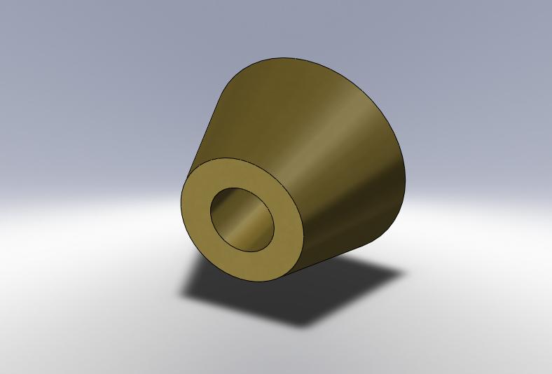 |
| Barrel Surrounds |
Manufacture - Class 2
I got a lot done in my second class of manufacture. Although the parts were quite simple I did not expect to get as many completed in a single lesson. The parts I got completed were:
Cams
To create my cams (x3, but all the same) I needed to:
- Sketch the outline of the cam
- Extrude the cam shape
- Use hole wizard to create the hole through the cam
 |
| My Cams |
Cam Shaft
To create my cam shaft all I needed to do was extrude a circle of the correct diameter
 |
| My Cam Shaft |
Key Barrel
The key barrel was my most complicated piece yet, to manufacture it I had to:
- Extrude a circle
- Sketch the key hole shape
- Extrude cut the key hole shape
- Use the hole wizard to bore the holes in the top of the barrel
 |
| My Key Barrel |
Solenoid Body
This was again a simple piece. All I needed to do was:
- Extrude a square
- Extrude cut a circle
 |
| My Solenoid Body |
Solenoid Pusher
The solenoid pusher was another easy part to make. It simply involved sketching the outline of the part and revolving the sketch to create the part.
 |
| My Solenoid Pusher |
Subscribe to:
Posts (Atom)